As the global demand for renewable energy surges, ballasted solar mounting systems for flat roofs have become a predominant solution for commercial, industrial, and large-scale residential projects. This article provides an in-depth analysis of the structural composition, functional principles, and installation procedures of these non-penetrating systems. It highlights their key advantages, including roof integrity preservation, cost-effectiveness, and design flexibility, supported by a real-world case study. The aim is to offer a practical and comprehensive reference for project planners, engineers, and installers.

1. Structural Composition and Functional Principle
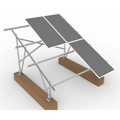
A ballasted flat roof mounting system is an engineering solution that uses gravity and friction to secure the entire photovoltaic array without penetrating the roof membrane. Its core components and functions are as follows:
Ballast (Concrete Blocks): This is the foundation of the system. The weight of the concrete blocks provides the counterforce against uplift forces from wind. The required ballast weight is meticulously calculated based on local wind speed, snow load, and the system's geometry.
Mounting Structure (Frames and Legs): Typically constructed from high-strength aluminum alloy (e.g., AL 6005-T5) and stainless steel (e.g., SUS304), this framework supports the PV panels. The structure includes adjustable legs to set the optimal tilt angle (usually between 5° to 15° for flat roofs) for maximizing solar energy harvest.
PV Panel Clamps (Mid and End Clamps): These specialized clamps, also made of corrosion-resistant materials, grip the edges of the solar panels, firmly attaching them to the mounting rails without drilling into the panels themselves.
Fasteners: Stainless steel bolts, nuts, and washers (SUS304) are used to connect all structural components, ensuring a rigid and durable assembly resistant to loosening from vibration or thermal cycling.
Functional Principle: The system operates on a simple yet effective principle of ballast and leverage. The concrete blocks, positioned at the base of the support legs, act as anchors. The weight of these blocks, combined with the low center of gravity of the entire array, creates a stable moment that resists overturning forces from wind suction. The system's design ensures that the downward force (gravity of ballast + system weight) always exceeds the upward lift force, guaranteeing stability.

2. Installation Steps: A Methodical Approach
Proper installation is critical for system performance and longevity. The process can be broken down into the following key stages:
Step 1: Site Survey and Load Analysis
Activity: A professional engineer must assess the roof's structural capacity to bear the additional dead load (weight of the system) and live loads (snow, maintenance personnel). The roof's condition, particularly the waterproofing membrane, is also thoroughly inspected.
Importance: This is the most critical step to ensure safety and avoid costly structural damage.
Step 2: System Layout and Ballast Mapping
Activity: Using CAD software, installers create a detailed layout plan. This plan maps the precise placement of every concrete block, rail, and panel. The ballast blocks are arranged in specific patterns to evenly distribute weight and optimize wind flow.
Step 3: Material Placement and Assembly
Activity: Concrete blocks are carefully placed on the roof according to the layout plan, often on protective pads to prevent abrasion of the roof membrane.
The aluminum support legs are then secured onto the blocks. The main rails are attached to these legs.
Note: No drilling into the roof deck occurs.
Step 4: PV Panel Installation
Activity: Solar panels are lifted onto the mounted rails. Mid-clamps and end-clamps are then used to securely fasten the panels to the rails. Electrical wiring and grounding are completed concurrently.
Step 5: Final Inspection and Commissioning
Activity: A comprehensive check is performed to verify the tightness of all clamps and bolts, the stability of the structure, the correctness of the electrical connections, and system grounding. The system is then commissioned for operation.

3. Key Considerations and Advantages
Key Considerations:
Structural Capacity: Never proceed without a verified structural analysis from a qualified engineer.
Roof Access & Maintenance: The layout must provide safe pathways for roof maintenance and access to existing equipment (e.g., HVAC units).
Wind Scour: In high-wind regions, the layout must consider how wind flows under the array to prevent potential uplift from wind tunneling effects.
Drainage: The system must not impede the roof's natural water drainage paths.
Product Advantages:
Zero Penetration, Maximum Integrity: Eliminates the risk of roof leaks, preserving the manufacturer's warranty and extending the roof's lifespan.
Cost and Labor Efficiency: Significantly faster installation reduces labor costs. The modular design allows for easy disassembly and reconfiguration if needed.
Superior Durability: The use of corrosion-resistant materials (Anodized Aluminum, Stainless Steel) ensures a long service life, often exceeding 25 years, even in harsh coastal environments.
Design Flexibility: Easily adaptable to complex roof shapes and obstructions. The tilt angle can be optimized for specific geographical locations.

4. Application Scenarios and a Success Case Study
Primary Application Scenarios:
Large-scale commercial buildings (warehouses, shopping malls, factories).
Industrial facilities and logistics centers.
Public institutions (schools, hospitals, government buildings).
Multi-family residential buildings (apartments).
Ground-mounted applications on sensitive surfaces where drilling is not permitted.
Case Study: "Logistics Hub"
Project: A 1.2 MW rooftop solar system for a large logistics warehouse in a coastal region.
Challenge: The roof consisted of a single-ply membrane with a valid warranty. The client demanded a solution with zero penetrations to avoid voiding the warranty and to withstand coastal corrosion and high wind speeds.
Solution: A custom-engineered ballasted system using AL 6005-T5 and SUS304 was deployed. The layout was optimized for wind load resistance (designed for 60m/s) and provided adequate ballast.
Result: The system was installed 30% faster than a penetrated system would have been. It has successfully withstood several typhoons, with no issues related to leaks or corrosion, and is consistently meeting its projected energy output, providing the client with significant energy cost savings.