Introduction
Proper installation is as critical as the solar components themselves. Even high-efficiency panels and inverters underperform-or become hazardous-if mounting structures are poorly installed. This guide covers essential safety protocols and quality benchmarks for PV system installation, with special focus on mounting structures (the backbone of any solar array).
1. Why Safety & Quality Matter in Installation
Structural integrity: Prevents module collapse, wind uplift, or snow load failure.
Electrical safety: Avoids DC arc faults, ground faults, and fire risks.
Worker safety: Reduces falls, electrocution, and handling injuries.
System longevity: Quality installation ensures 25+ years of trouble-free operation.
Warranty compliance: Most manufacturers (including Longsun Green) require adherence to specified installation standards.
2. Key Safety Hazards & Prevention Measures
| Hazard | Prevention |
|---|---|
| Falls from height (roofs, ladders) | Guardrails, safety harnesses with anchor points, scaffolding |
| Electrocution (live DC cables) | Disconnect AC/DC before work; use insulated tools; cover panels |
| Fire (arc faults, hot spots) | Proper DC isolation; torque-limiting tools for connections |
| Structural collapse (overloading) | Verify roof load capacity; use lightweight mounting systems |
| Module breakage (glass) | Handle with suction cups; avoid stepping on panels |
| Sharp edges (rails, flashings) | Cut-resistant gloves; deburr cut ends |

3. Quality Standards for Mounting Structures (Focus Area for Longsun Green)
The mounting structure transfers all mechanical loads to the building or ground. Quality criteria include:
A. Material Quality
Aluminum (6005-T5 / 6063-T6): Anodized (≥15μm) for corrosion resistance
Stainless steel bolts (A2-70 / A4-80): Anti-galling, salt-spray resistant
Galvanized steel (Z275 / HDG): For ground mounts or high-humidity zones
B. Installation Quality Checks
| Check Point | Standard |
|---|---|
| Rail alignment | Straight within ±2 mm per 10 m |
| Clamp torque | 16–20 Nm (check manufacturer spec) |
| Module gap | 5–10 mm between modules (thermal expansion) |
| Grounding continuity | <0.1 Ω between all metal parts |
| Tilt angle deviation | ≤ ±2° from design |
| Wind uplift resistance | Matches structural calculation (e.g., 3,600 Pa) |
C. Roof-Specific Requirements
Penetrations: Sealed with EPDM/butyl flashing + silicone sealant
Waterproofing: No damage to underlying membrane; install standoffs if needed
Rail splicing: Minimum 200 mm overlap with two bolts
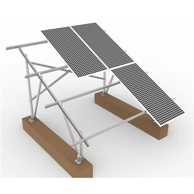
D. Ground-Mount Specifics
Foundation depth: Below frost line (typically 0.8–1.2 m)
Concrete grade: ≥C25 (if used)
Corrosion protection: For direct burial, HDG coating or stainless steel
4. Functional Principle of Proper Installation
A correctly installed mounting system ensures:
Load path continuity: Snow/wind → module → clamp → rail → structure → foundation → ground.
Electrical continuity: All metal parts bonded → grounding lug → inverter grounding terminal.
Thermal movement: Slotted holes and end clamps allow ±3 mm expansion per 10 m rail.
Drainage: No water pooling; rails have weep holes or slope ≥1°.
5. Application Scenarios & Their Specific Safety Measures
| Scenario | Key Risks | Extra Quality Measures |
|---|---|---|
| Pitched roof (tile/slate) | Broken tiles, hidden leaks | Use tile hooks; install flashing under tile course |
| Flat roof (membrane) | Puncture, wind uplift | Ballasted or penetrating-free systems; wind deflectors |
| Metal standing seam | Clamp slippage | Seam-height-matched clamps; rubber inserts |
| Ground farm | Grounding corrosion, uneven terrain | Copper bond at each row; adjustable piles |
| Solar carport | Vehicle safety, cantilever load | Bollards or barriers; double-check anchor bolts |
| Agrivoltaics (above crops) | Dropped tools/modules | Safety nets; two-person lift for all panels |
6. Required Personal Protective Equipment (PPE)
Fall protection: Full-body harness + lanyard (if roof slope >25°)
Head protection: Hard hat (especially for ground mounts)
Hand protection: Cut-resistant gloves (level 3–5) + insulated electrical gloves
Foot protection: Non-slip, steel-toe boots
Eye protection: Safety glasses (during drilling or cutting)
7. Pre-Installation & Post-Installation Checklist
Pre-installation:
Structural assessment report (roof age, load capacity)
Wind/snow load calculation (local code)
Torque wrench calibrated
All mounting parts from same batch (Longsun Green ensures batch traceability)
Weather forecast (no rain, wind <5 m/s for panel handling)
Post-installation:
Thermal imaging scan (no hot spots)
Grounding resistance test (<1 Ω to earth)
Torque spot-check (≥10% of clamps)
Waterproofing test (hose spray on flashings)
Documentation: as-built drawings, torque logs, photos

8. Common Installation Mistakes & How to Avoid Them
| Mistake | Consequence | Prevention |
|---|---|---|
| Over-torquing clamps | Micro-cracks in glass | Use torque wrench, not impact driver |
| Missing end clamps | Module slides off rail | Follow BOM exactly |
| No anti-corrosion paste on bolts | Galvanic corrosion (aluminum + steel) | Use Tef-Gel or similar |
| Rails not grounded | Electric shock risk | Install grounding lug every 10 m |
| Ignoring module frame holes | Water ingress into frame | Use designated mounting holes only |
9. Standards & Certifications to Reference
| Standard | Scope |
|---|---|
| IEC 62548 | PV array installation requirements |
| IEC 61730 | Module safety qualification |
| UL 2703 | Mounting system grounding & bonding (North America) |
| AS/NZS 5033 | Australian installation standard |
| EN 1991 (Eurocode 1) | Wind & snow loads on structures |
Conclusion
Safe and quality installation is not optional-it is the foundation of a profitable, long-lasting solar asset. By following the safety protocols and quality standards outlined above, installers can prevent accidents, maximize energy yield, and protect end-user investments.
For mounting structures engineered with safety in mind, Longsun Green provides reliable, code-compliant solutions backed by technical support.