Mounting rooftop PV blends fall hazards, roof waterproofing, and structural loads. Use full-body fall protection, follow tool manufacturers' instructions, and comply with local building/electrical codes. If any step exceeds your license or experience-especially structural anchorage and electrical tie-in-hire qualified pros.
Step 1 - Pre-Mounting Checklist
Roof Condition & Remaining Life
Solar stays 20–30 years; if shingles/membrane are near end-of-life, re-roof before PV.
Structure Capacity
Confirm rafter/truss size, spacing, spans, and allowable loads. PV adds ~12–18 kg/m² (2.5–3.5 psf) plus wind/snow uplift-a structural review is smart in high wind/snow regions.
Code, Permits & Fire Setbacks
Most jurisdictions require permits and firefighter access pathways/ridge setbacks. Plan your array outline accordingly.
Array Orientation & Standoff
Meet the roof's pitch and keep a small standoff gap (typically 2.5–10 cm) under modules for airflow; cooling improves output and roof longevity.
Step 2 - Choose Your Mounting Architecture
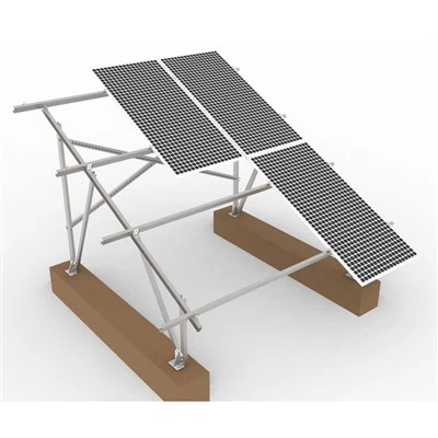
Rail-Based Systems (most common)
Aluminum rails span between roof attachments; modules clamp to rails. Pros: easy leveling, robust wire management, wide roof compatibility.
Rail-Less Systems
Module frames attach directly to roof mounts with integrated clamps. Pros: fewer parts, lighter; Cons: tighter layout tolerances, more care leveling.
Attachment Strategy
Into structure, not sheathing. Fasteners must engage rafters or purlins with manufacturer-specified embedment.
Expansion & Conductivity. Provide rail expansion joints; ensure bonding between all metallic parts for grounding.
Wind & Snow Engineering
Use the racking manufacturer's span tables for your wind exposure, height, and ground snow load to determine attachment spacing and rail spans.
Step 3 - Roof-Type Specific Attachments
A) Asphalt/Composite Shingle
Hardware: Flashed L-feet or standoffs with lag screws into rafters.
Method:
Locate rafters (stud finder + attic check).
Lift shingle course carefully; slide metal flashing so the upper edge is under the shingle above.
Predrill pilot hole into the rafter; inject manufacturer-approved sealant in the hole (if specified).
Drive lag screw to torque spec; the flashing is your primary waterproofing-never rely on caulk alone.
Tips: Keep fasteners high on the shingle, align rows with snapped chalk lines, and maintain parallel rails for clean aesthetics.
B) Standing-Seam Metal
Hardware: Seam clamps (e.g., set-screw or pinch-type) that grip the seam-no penetrations.
Method:
Verify seam type (snap-lock vs mechanically seamed) and panel gauge.
Locate clamp positions per engineering; tighten to published torque.
Attach rails to clamps; respect thermal expansion gaps.
Tips: Do not crush seams; avoid clamp placement on panel clips unless allowed.
C) Corrugated/Trapezoidal Metal (Through-Fastened)
Hardware: Crest-mounted brackets with EPDM gaskets or specialized rail-less feet; structural purlin fasten.
Method:
Pre-drill crest; apply butyl/EPDM gasket; fasten with listed self-drilling screws into purlin.
Add rails or direct-mount clamps; seal per instructions.
Tips: Fasten on high ribs (crests) for drainage; avoid valley penetrations.
D) Tile Roof (Concrete/Clay/Spanish "S")
Principle: Do not bear on tile; anchor to deck/rafter beneath.
Hardware: Tile hooks or replace-tile flashings with baseplates and raised posts.
Method:
Remove tile; mount base to structure; integrate a flashing pan under the upper course.
Reinstall/trim tile to clear the post or use a formed replacement flashing tile.
Tips: Clay is brittle-use tile cutters, pads, and avoid point loads. Keep underlayment intact and resealed.
E) Low-Slope Membrane (TPO/PVC/EPDM)
Options: Ballasted racking (weight-based) or mechanically attached stanchions with membrane boots.
Notes: Always coordinate with a commercial roofer; membrane welding and warranty continuity are critical.
Step 4 - Layout, Marking & Attachment
Snap Control Lines parallel to eaves/ridge; this keeps attachments and rails in straight rows.
Mark Rafters/Purlins across the array area; lay out mount spacing from the racking span table.
Install Attachments (flashed L-feet, clamps, brackets) to torque spec; wipe off excess sealant.
Set Rails (if rail-based):
Level and square; use rail splices per manufacturer; integrate bonding splices or add jumpers.
Check cantilever limits at rail ends (often 30–40 cm, per spec).
Verify Standoff Height uniformly for airflow and to clear roof undulations.
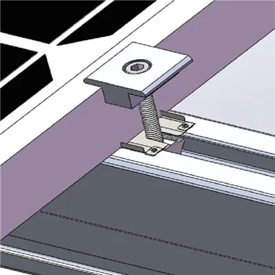
Step 5 - Module Mounting & Clamping
Clamping Zones: Every module datasheet shows allowed clamp locations (end vs mid-span). Never clamp outside these zones.
Mid/End Clamps: Torque to spec; keep consistent gaps between modules.
Level & Plane: Sight along rows; adjust feet/rail levels to prevent twisting modules.
Wire Management: Use UV-rated stainless clips under the module frames; create drip loops; keep conductors off hot/sharp surfaces.
Step 6 - Bonding, Grounding & Penetrations
Bond All Metal Parts: Many rails/clamps have integral bonding teeth; add ground lugs where rails break or jump to other metal. Terminate to the equipment grounding conductor sized per code.
Roof Penetrations: For any junction box/conduit, use listed flashed boots with counter-flashing; seal only as specified.
Thermal Expansion: Leave slack and gentle bends; provide rail expansion joints as directed.
Step 7 - Quality-Control & Final Checks
Mechanical QC
Attachments torqued; flashing seated; no lifted shingles or cracked tiles.
Rails square/level; splices bonded; cantilevers within limits.
Modules clamped in allowed zones; all hardware stainless/aluminum as specified.
Waterproofing QC
All penetrations flashed (not just caulked); conduits have rain hats/drip loops.
No penetrations in valleys; sealant compatible with roofing materials.
Electrical Readiness (Mounting-Adjacent)
Wire routes secured; no abrasion points; labels ready; rapid-shutdown equipment in place (where required).
Grounds continuous and landed; no floating rails.
Common Mistakes (And Better Practices)
Missing Structure → Pull-outs/Leaks
Fix: Confirm rafters from both the roof and attic; pre-drill; measure embedment.
Relying on Caulk Instead of Flashing
Fix: Flashings are the primary defense; sealant only supplements what's flashed.
Over-Spacing Attachments
Fix: Use the manufacturer's span tables for your wind/snow zone and roof sheathing.
Clamp Outside Allowed Zones
Fix: Follow module clamp diagrams; wrong clamping risks glass/frame stress and voids warranties.
Wire Sag & UV Damage
Fix: Stainless/UV-rated clips at regular intervals (about every 30–45 cm); keep cables shaded under array when possible.
No Provision For Expansion
Fix: Add expansion splices/gaps; avoid hard-anchoring long continuous rails.
Tile Breakage
Fix: Use replace-tile flashings or hooks correctly; never shim on tile; carry spare tiles.
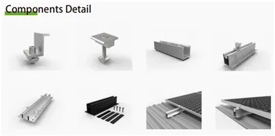
Tools & Materials (Mounting Core)
Fall-arrest gear (harness, anchors, lifeline), roof-safe ladder with standoff
Stud/rafter finder, chalk line, level, tape, drill/driver, impact + sockets
Rail system or rail-less mounts, flashed L-feet / clamps / brackets
Stainless mid/end clamps, bonding splices/lugs, equipment ground conductor
UV-rated wire clips, conduit/roof boots, compatible sealants/butyl/EPDM gaskets
Torque wrench (document torque for inspection)
FAQ
Do I need to hit every rafter?
Follow the racking span table. Attachment spacing depends on wind/snow, rail strength, and module size; you'll typically use many rafters, not every one.
How high should modules sit off the roof?
Just enough for airflow and drainage while minimizing wind profile-often 25–100 mm depending on hardware and climate.
Can I mount over new shingles without voiding the roof warranty?
Use listed flashing systems approved by the roofing manufacturer; many warranties remain valid when specified products are used correctly.
Are penetrations avoidable?
Yes on standing-seam metal using seam clamps. Other roofs typically require flashed penetrations or specialty methods coordinated with the roofer (membranes).