Mounting PV modules combines falls, structure, weatherproofing, and high-voltage DC. Wear fall protection, follow manufacturer manuals, and comply with local building/electrical codes. If any step (especially structural anchorage or electrical interconnection) exceeds your experience or licensing, bring in a qualified pro.
Step 1 - Site & Load Assessment
Sun & Shade. Confirm unshaded sun windows (roughly 9:00–15:00). Even small obstructions (chimneys, parapets, trees) can cut output; consider module-level power electronics in partial shade.
Orientation & Tilt. Point arrays equator-facing (south in N. Hemisphere / north in S.), tilt near your latitude or the roof pitch. Ground arrays can be racked to the desired tilt.
Structure & Loads. Determine rafter/truss or purlin layout, sheathing thickness, and spans. PV adds ~12–18 kg/m² (2.5–3.5 psf) plus wind uplift and snow. Use racking span tables and, in high wind/snow or old structures, get a structural review.
Roof Condition. Solar stays 20–30 years. If roofing has ≤5 years left, re-roof before PV.
Permits & Setbacks. Most jurisdictions require building/electrical permits, utility interconnection, and firefighter access pathways on roofs.
Step 2 - Choose A Mounting Architecture
A) Roof Mounts
Rail-Based (most common): Aluminum rails span between attachments into structure; modules clamp to rails (mid/end clamps).
Pros: Easy leveling, clean wire management, wide roof compatibility.
Cons: More parts than rail-less.
Rail-Less: Module frames attach directly to roof mounts.
Pros: Fewer parts, lighter.
Cons: Tighter layout tolerances; leveling takes care.
Attachment by roof type
Asphalt/Composite Shingle: Flashed L-feet lag-bolted into rafters. Flashing is the primary waterproofing-never rely on caulk alone.
Standing-Seam Metal: Seam clamps grip the seams-often no penetrations. Respect clamp torque and thermal expansion.
Corrugated/Trapezoidal Metal: Crest-mounted brackets with EPDM gaskets into purlins; avoid valley penetrations.
Tile (clay/concrete): Never load tile. Use hooks or replace-tile flashings mounted to structure with flashing pans beneath the upper course.
Low-Slope Membrane (TPO/PVC/EPDM): Ballasted racks (weight-based) or mechanically attached stanchions with welded boots-coordinate with a commercial roofer to maintain membrane warranty.
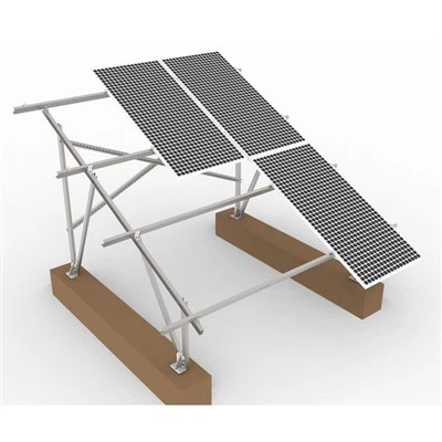
B) Ground Mounts
Fixed-Tilt: Posts in concrete footings or driven piles support rails. Best for yards/fields; easy to clean and expand.
Pole Mounts: One or more modules on a single steel pole with tilt adjust; compact footprint.
Trackers (single-axis): Boost yield by following the sun; require robust foundations, motors, and O&M-more common in utility scale.
C) Carports & Canopies
Provide shade and PV generation simultaneously; require structural steel and engineered connections-great for commercial lots or patios.
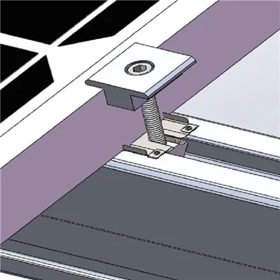
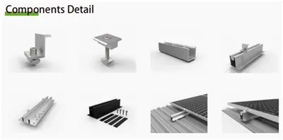
Step 3 - Hardware, Holes & Clamp Zones
Use the factory provisions. Framed modules usually have pre-drilled mounting holes/slots on the back frame and specified clamp zones along the frame edges. Follow the module manual; do not drill new holes in frames or glass (warranty/certification risk).
Fasteners. Typical stainless M8 (5/16") with flat + lock washers; torque as specified. Use isolation where contacting galvanized steel to reduce galvanic corrosion.
Bonding. Many rails/clamps have integrated bonding teeth (UL 2703 or regional equivalent). Otherwise, use listed grounding lugs at the module's earthing hole.
Step 4 - Layout, Marking & Attachment (Roof Example)
Find Structure. Locate rafters/purlins from attic and roof; snap chalk lines parallel to ridge/eave to keep rows straight.
Install Attachments.
Shingle: slide flashing under the upper course; pilot-drill and lag into rafter; seal per the flashing spec.
Metal seam: set seam clamps to manufacturer torque.
Tile: remove tile, mount base to structure, install flashing pan, then trim/replace tile to clear post.
Rails On. Level and square rails; respect rail cantilever limits; splice rails with bonding splices.
Standoff & Cooling. Maintain a small uniform gap (≈25–100 mm) under modules for airflow and roof longevity.
Step 5 - Module Mounting & Wire Management
Clamping. Place mid/end clamps strictly within allowed clamp zones; torque evenly to avoid frame distortion.
Wire Runs. Keep conductors shaded under the array; form drip loops before entry points; use UV-rated stainless clips and listed roof boots for penetrations. Avoid sharp edges and hot surfaces.
Electronics.
Microinverters mount at module level (often to rails); simplify DC wiring.
Optimizers + String Inverter add module-level MPPT/monitoring with centralized AC.
String Inverter only suits uniform, shade-free arrays.
Follow string sizing (Voc at lowest temperature, Isc, MPPT windows) and rapid-shutdown rules where applicable.
Step 6 - Ground Mount Workflow (Quick Outline)
Layout & Setbacks. Stake array corners, maintain property and utility easements.
Foundations. Excavate and pour concrete footings or drive steel piles to engineered depth; align post tops to plane.
Racking. Attach horizontal rails or truss members; square and level the plane.
Modules & Wiring. Clamp modules, land homeruns in combiner or trunk cable, bond all metal.
Fencing & Vegetation. Keep growth below module edges; maintain clear access for O&M.
Step 7 - Weatherproofing & Expansion
Flashing first, sealant second. Every roof penetration gets a listed flashing; sealant only supplements.
Thermal Movement. Use rail expansion joints and slotted holes as specified; leave wire slack with gentle bends.
Drainage. Do not block module weep holes; keep conduit penetrations high on shingle courses; add rain hats where exposed.
Step 8 - Commissioning & QA (Mechanical Adjacent)
Mechanical QA. Verify torque on attachments, rail splices, and clamps; ensure no wire chafes; confirm standoff and clear pathways for fire access.
Labeling. Apply permanent labels at disconnects, service equipment, and rooftop per code.
Photos & Records. Document serial numbers, attachment patterns, torque settings, and as-built one-line.
Common Mistakes (And Better Practices)
Missing structure / weak embedment → pull-outs & leaks. Always pilot-drill and confirm embedment into rafters/purlins; never depend on sheathing alone.
Over-reliance on caulk. Flashing does the waterproofing; caulk is not a substitute.
Clamping outside allowed zones. Can crack glass or fail load ratings-follow the module diagram.
Wire sag & UV damage. Use stainless/UV clips every 30–45 cm; keep runs shaded under array.
Ignoring thermal expansion. Provide expansion splices and cable slack; don't hard-anchor long rails end-to-end.
Tile breakage. Don't bear on tile; use hooks/replace-tile flashings and carry spares.
Tools & Materials (Core List)
Fall-arrest gear (harness, anchors, lifeline), ladder with standoff
Stud/rafter finder, chalk line, level, tape, drill/driver, impact + sockets, torque wrench
Rail system or rail-less mounts; flashed L-feet/clamps/brackets per roof type
Stainless mid/end clamps, bonding splices/lugs, equipment grounding conductor
UV-rated wire clips, EMT or UV conduit, roof boots, compatible sealants/butyl/EPDM gaskets
FAQ
Can I avoid penetrations?
On standing-seam metal, yes (seam clamps). Otherwise, use flashed penetrations or coordinate membrane boots; ballasted racks avoid penetrations on some flat roofs but add weight and wind design complexity.
How high should modules sit off the surface?
Just enough for airflow and drainage while limiting wind profile-typically 25–100 mm depending on hardware and climate.
Do panels have mounting holes on the back?
Framed modules usually have factory holes/slots on the rear frame; frameless modules rely on edge clamps or tested point supports.
What about lightning or surge?
Bond properly and consider surge protective devices on DC and AC where recommended, especially in lightning-prone areas.