1. Cleaning Requirements for Photovoltaic Modules
1.1 When to Clean
Regular cleaning is essential to maintain optimal power generation efficiency. According to China's technical standard T/CAPE 11005-2023, cleaning decisions should be based on:
Power loss assessment: When soiling-induced power loss exceeds 5% of rated output
Visual inspection: Noticeable accumulation of dust, bird droppings, leaves, or industrial residue
Seasonal factors: Pollen seasons, dry periods with minimal rainfall, or post-construction debris
1.2 Cleaning Methods
Water Cleaning (Standard Method)
Use demineralized or low-mineral water to prevent spotting and scaling
Water pressure should not exceed 5 MPa to avoid module glass damage
Cleaning temperature range: 5°C to 35°C (avoid extreme thermal shock)
Mechanical Cleaning
Soft roller brushes or microfiber pads are recommended
Automated cleaning robots suitable for utility-scale ground-mounted systems
Avoid abrasive tools that may cause micro-scratches on anti-reflective coating
1.3 Safety Considerations
All cleaning personnel must be properly trained for working at height
For rooftop systems, fall protection equipment and safety harnesses are mandatory
Never clean modules during operation if electrical hazards exist; systems should be shut down or cleaned at night/early morning
Avoid stepping directly on solar modules - use designated walkways or mounting rails
1.4 Functional Principle
Dust and soiling reduce light transmission to the photovoltaic cells through two mechanisms:
Absorption: Particles absorb incident sunlight before reaching the glass surface
Scattering: Particulate matter scatters light away from the module active area
This soiling effect can reduce annual energy yield by 5-25% depending on the installation environment (desert, agricultural, or industrial areas).
2. Lightning Protection and Grounding Systems
2.1 Why Lightning Protection Matters
Photovoltaic power plants, by virtue of their outdoor exposure and large surface area, are particularly vulnerable to lightning strikes . A direct or nearby strike can induce voltage surges reaching tens of thousands of volts, leading to:
Inverter and charge controller damage
Fire hazards from arcing
Complete system shutdown and costly repairs
Personnel safety risks during maintenance
2.2 Key Components
Air Terminals (Lightning Rods)
Installed at elevated points above the array
Typically made of round steel rods (12-16mm diameter) with hot-dip galvanized coating
Function: Capture the lightning discharge and direct it safely downward
Down Conductors
Transport lightning current from air terminals to ground
Preferred materials: Hot-dip galvanized round steel or flat steel (minimum 40mm × 4mm cross-section)
Spacing between down conductors should follow local electrical codes
Grounding Electrodes
Dissipate lightning energy into the earth
Common specifications:
Steel pipe: Minimum 50mm diameter, 3.5mm wall thickness
Angle steel: 50mm × 50mm × 5mm
Horizontal grounding conductors buried at least 0.5m depth (below frost line)
Vertical electrodes driven 2.5m or deeper
Equipotential Bonding
Ensures all metal components maintain the same voltage during a surge event
Module frames and mounting rails must be bonded together using 4mm² yellow-green conductors
Prevents side-flashing (arc discharge) between components at different potentials

2.3 Best Practices for PV Plants
Separation of Grounding Systems
Equipment grounding and lightning protection grounding should be kept separate
Maintain minimum 10m distance between different grounding conductor paths
Critical: Never connect inverter PE (protective earth) directly to lightning down conductors
Surge Protection Devices (SPDs)
Install Type 1 SPDs at the DC input of inverters (Iimp ≥ 5kA, 10/350μs waveform)
Install Type 2 SPDs at AC grid connection points
Always install a circuit breaker or fuse ahead of SPDs to prevent fire if the SPD fails
Shielding
Use metallic conduit or cable trays with grounding continuity
Enclose sensitive electronics in grounded metallic enclosures (LPZ protection zones)
2.4 Application Scenarios
| Scenario | Critical Requirements |
|---|---|
| Ground-mounted plants (open field) | Comprehensive external lightning protection; deep grounding rods |
| Rooftop commercial systems | Bonding to building structural steel; existing lightning protection system integration |
| High-lightning regions (tropical/ subtropical) | Redundant grounding paths; higher-rated SPDs |
3. Wind Resistance Requirements
3.1 Structural Principles
Wind loads on PV modules create both uplift (lifting force) and downward pressure. The magnitude depends on:
Array tilt angle: Higher tilt angles increase wind exposure
Module row spacing: Wind acceleration between rows can amplify forces
Installation height: Elevated structures experience higher wind speeds
Terrain category: Open fields have higher design wind speeds than urban areas
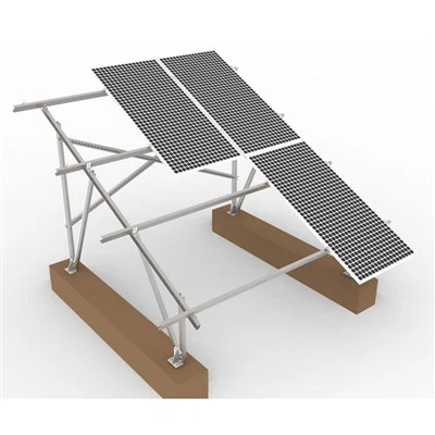
Modern mounting systems are designed using spatial cable–truss architecture, where tensioned pre-stress elements distribute loads more effectively than conventional rigid frames . Under wind loading, the structure flexes slightly, converting kinetic wind energy into structural tension without permanent deformation.
3.2 Testing and Standards
ASCE 7-22 (USA)
Updated every six years by the American Society of Civil Engineers
Introduces new wind, snow, seismic, and tornado load criteria
Design wind speeds are based on 700-year return period events
CSA C451 (Canada – Draft 2026)
Laboratory test method for dynamic wind load resistance
Applies to arrays with tilt angle ≤35° from roof surface
Uses hydraulic or pneumatic actuators to simulate cyclic wind loading
Wind Tunnel Testing
For large-scale or unconventional designs, physical wind tunnel validation is recommended
Recent research on double-row flexible PV supports shows wind direction and inclination angle significantly impact pressure distribution
Maximum wind pressure coefficients can reach -1.572 (uplift) at corner zones
3.3 Design Recommendations
| Component | Requirement |
|---|---|
| Mounting rails | Extruded aluminum (6005-T5 or 6063-T5) or galvanized steel (Q235B/Q355B) |
| Fasteners | Stainless steel (A2-70 minimum) with anti-vibration locking washers |
| Foundation | Ballasted, driven pile, or helical anchor depending on soil conditions |
| Module-to-rail clamps | Designed for specified mechanical load rating (e.g., 2400Pa/5400Pa) |
3.4 Case Study: Typhoon Resilience
A 70 MW fishery complementary PV project in Hainan successfully withstood Super Typhoon Yagi (Category 17 equivalent) using flexible mounting technology. Post-storm inspection by TÜV confirmed:
No module deformation or glass breakage
No micro-cracks detected
No structural compromise
3.5 Application Scenarios by Wind Zone
| Wind Zone | Typical Region | Design Speed | Recommended Structure |
|---|---|---|---|
| Low | Inland valleys | < 30 m/s | Standard ballasted or ground screw |
| Medium | Coastal plains | 30-42 m/s | Driven piles + diagonal bracing |
| High | Typhoon-prone / Cyclone regions | > 42 m/s | Flexible cable-trc1ss or heavy steel frame |

4. Snow Load Requirements
4.1 Functional Challenge
Snow accumulation on PV modules creates three distinct risks:
Mechanical overload: Excessive weight can exceed the module's mechanical load rating (typically 5400Pa or ~550 kg/m²)
Non-uniform distribution: Drifting and sliding snow creates uneven loading that concentrates stress
Power loss: Snow cover completely blocks light transmission, reducing output to near zero
4.2 Standards and Testing
GB/T 46988-2025 / IEC 62938:2020
China's upcoming national standard (effective July 1, 2026)
Equivalent to international IEC standard
Defines non-uniform snow load testing methodology
Simulates realistic snow drift patterns rather than assuming uniform blanket coverage
ASCE 7-22 Snow Updates
Net increase in design snow loads: 10-20% across many US regions
Lower load factors but higher thermal factors for snow melting/refreezing cycles
May require closer rail spacing or additional purlins in high-snow areas
4.3 Design Strategies for Snow-Prone Regions
Active Removal Measures
Roof-mounted systems with tilt angles ≥30° promote natural snow sliding
Heating elements embedded in modules (available as premium option)
Manual removal using foam snow rakes (never metal tools)
Structural Measures
Increased rail density (reduced spacing between support points)
Enhanced end clamps to prevent modules from sliding downward
Stop blocks or snow guards at array lower edge
4.4 Application Scenarios
| Snow Load Zone | Typical Snow Depth | Design Load | Recommendation |
|---|---|---|---|
| Low | < 50 cm | ≤ 2400Pa | Standard mounting ok |
| Medium | 50-150 cm | 2400-5400Pa | Reduce rail spacing; consider tilt >30° |
| High | > 150 cm | ≥ 5400Pa | Active removal recommended; snow guards |
Summary Table: Environmental Requirements at a Glance
| Factor | Key Standard | Critical Parameter | Failure Consequence |
|---|---|---|---|
| Cleaning | T/CAPE 11005-2023 | Pressure ≤5 MPa; T=5-35°C | Hot spots, delamination |
| Lightning | IEC 62305 | Iimp ≥5kA (10/350μs) | Inverter destruction, fire |
| Wind | ASCE 7-22 / CSA C451 | Depends on zone (30-50+ m/s) | Module loss, structural collapse |
| Snow | IEC 62938 / GB/T 46988-2025 | Non-uniform load test | Frame bending, glass fracture |

References
Solar Energy UK. Rooftop O&M Guidelines 3.0 (2025)
Growatt. The Ultimate Guide to Lightning Protection and Grounding for C&I PV Power Plants (2025)
CSA Group. Draft Standard C451: Dynamic Wind Load Resistance of Photovoltaic Roof Assembly (2026)
Unirac. Solar Mounting Systems Built to ASCE 7-22 Standards (2026)
DAS Solar. Flexible Mounting Systems for Complex Terrain (2025)
China Standard T/CAPE 11005-2023. Technical Specifications for PV Module Cleaning
SOLARZOOM. Lightning Protection and Grounding for Grid-Connected PV Systems
Journal of Wind Engineering. Double-row PV Panel Aerodynamic Characteristics (2024)
China Standard GB/T 46988-2025 / IEC 62938:2020. Non-uniform Snow Load Testing
Longsun Green
Longsun Green is a professional manufacturer of solar mounting structures for residential, commercial, and utility-scale applications. Our products are engineered to meet international wind, snow, and seismic standards.
📧 amber@longsungreen.com | 🌐 www.longsungreen.com